Transformers and transmission of electricity
Transformers are devices that transfer electric power from one circuit to another using electromagnetic induction. For simplicity, we assume that transformers are ideal, meaning they operate at \(100\%\) efficiency, with no energy lost in the process.
Transformers are used to modify voltage levels, usually to either minimise power loss during long-distance transmission, or to convert to the required voltage for a specific purpose. For instance, household mains electricity is \(240 \text{ V}\), however many laptops only require \(7 -10 \mathrm{~V}\) to be charged. Hence, laptop chargers contain a transformer to convert the voltage to the required level.
Use this page to revise the following concepts within transformers and transmission of electricity:
How does a transformer work?
A transformer typically consists of two coils of wire, a primary coil and a secondary coil, both wrapped around a common iron core.

Within the transformer, an AC current is supplied to the primary coil. This AC current generates a changing magnetic field in the iron core. The changing field passes through the secondary coil via the core. As a result, there is a changing flux in the secondary coil, which induces which induces an emf, and therefore a current, in the secondary coil.
NoteA transformer only works with an AC input. If a DC power source is used in the primary coil, there is no change in magnetic flux, so no current is induced in the secondary coil. |
The Transformer Equation
As a direct result of Faraday’s law, there is a relationship between the number of turns in the coil and the voltages in the primary and secondary coils.
For an ideal transformer:
Where:
- \(V_1\) is the voltage in the primary coil \((\mathrm{V})\)
- \(V_2\) is the voltage in the secondary coil \((\mathrm{V})\)
- \(N_1\) is the number of turns in the primary coil
- \(N_2\) is the number of turns in the secondary coil
Transformers can be designed to increase or decrease voltage:
- If \(N_2>N_1\) the transformer is called a step-up transformer – it increases the voltage in the secondary coil.
- If \(N_1>N_2\) the transformer is called a step-down transformer – it decreases the voltage in the secondary coil.
Transformers are often described using a turns ratio. For example, a transformer with \(a\) turns in the primary coil and \(b\) turns in the secondary coil is said to be a \(a:b\) transformer.
Worked Example
The transformer in an appliance consists of a primary coil with \(500\) turns, an input AC voltage of \(240 \text{ V}\) and a secondary coil with \(25\) turns. Determine the voltage in the secondary coil.
Solution
Identify variables and substitute into the formula for an ideal transformer
\[ \begin{align*} \frac{240}{V_2} &= \frac{500}{25} \\ \frac{V_2}{240} &= \frac{25}{500} \\ V_2 &= \frac{25}{500} \times 240 = 12 \ \text{V} \end{align*} \]
Check your understanding
View

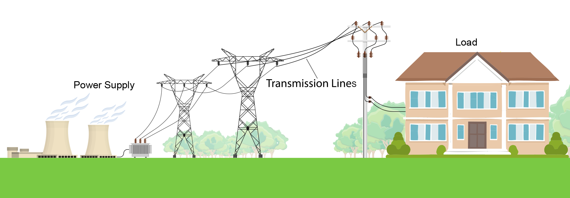
Transmission of power
In addition to adjusting voltages for appliances, transformers are essential for transmitting electrical power over long distances with minimal energy loss.
Even though transmission wires have relatively low resistance, the large distances involved in power distribution mean that power loss due to resistance can become significant.
We can model the delivery of electrical power to a load, such as a house, using basic electrical equations.
The voltage drop across the transmission lines is given by:
\[ V_{\text{drop}} = I_{\text{lines}} \times R_{\text{lines}} \]
Where:
- \(V_{\text{drop}}\) is the voltage drop across the transmission lines \((\mathrm{V})\)
- \(I_{\text{lines}}\) is the current in the transmission lines \((\mathrm{A})\)
- \(R_{\text{lines}}\) is the resistance of the transmission lines (\(\Omega\))
Hence, the voltage delivered to the load is then:
\[ V_{\text{load}} = V_{\text{supply}} - V_{\text{drop}} \]
The power loss in the transmission lines is given by:
\[ P_{\text{loss}} = V_{\text{drop}} \cdot R_{\text{drop}} \quad \text{or} \quad P_{\text{loss}} = I_{\text{lines}}^2 \cdot R_{\text{lines}} \]
Where:
- \(P_{\text{loss}}\) is the power loss in transmission (\(\text{ W}\))
- \(V_{\text{drop}}\) is the voltage drop across the transmission lines (\(\text{ V}\))
- \(I_{\text{lines}}\) is the current in the transmission lines (\(\text{ A}\))
- \(R_{\text{lines}}\) is the resistance of the transmission lines (\(\Omega\))
Similarly, the power delivered to the load is then:
\[ P_{\text{load}} = P_{\text{supply}} - P_{\text{loss}} \]
In order to reduce the power loss, two options are available:
- Decrease the resistance of the power lines. This can be done by increasing their cross-sectional area or choosing a more conductive material. These have their limitations however; such as increased cost and weight.
- Decrease the current in the power lines. This is more effective as power loss is proportional to the square of the current (\(P_{\text{loss}} \propto I_{\text{lines}}^2\)) compared to directly proportional to the resistance (\(P_{\text{loss}} \propto R\)).
To reduce current while keeping power constant, step-up transformers are used at the generation end. These increase the voltage and thus allow the current to decrease during transmission. At the receiving end, step-down transformers reduce the voltage to a safe and usable level for homes and businesses.
\[
P = VI \quad \Rightarrow \quad \text{if } V \uparrow, \text{ then } I \downarrow
\]
At the receiving end, step-down transformers reduce the voltage to a safe and usable level for homes and businesses.
To account for current, the ideal transformer equation can be extended. For an ideal transformer:
\[ \frac{V_1}{V_2} = \frac{N_1}{N_2} = \frac{I_2}{I_1} \]
Where:
- \(V_1\) is the voltage in the primary coil (\(\text{ V}\))
- \(V_2\) is the voltage in the secondary coil (\(\text{ V}\))
- \(N_1\) is the number of turns in the primary coil
- \(N_2\) is the number of turns in the secondary coil
- \(I_1\) is the current in the primary coil (\(\text{ A}\))
- \(I_2\) is the current in the secondary coil (\(\text{ A}\))
Worked Example
Consider the power being delivered to a house with and without transformers
Without transformers
If a power supply of \(100\text{ W}\) and \(250\text{ V}\) is to be delivered to a house (load), by first being transmitted by two transmission lines, each with a resistance of \(50.0\ \Omega\), what is the voltage and power supplied to the load?
Solution
- First, determine the current through the wires:\[ P = VI, \quad I = \frac{100}{250} = 0.4 \ \text{A} \]
- Determine the voltage drop in the lines: \[ V_{\text{drop}} = I_{\text{lines}} \cdot R_{\text{lines}}, \quad V = 0.4 \times 100 = 40 \ \text{V} \]
- Determine the voltage delivered to the load:\[ V_{\text{load}} = V_{\text{supply}} - V_{\text{drop}} = 250 - 40 = 210 \ \text{V} \]
- Determine the power loss in the lines:\[ P_{\text{loss}} = I_{\text{lines}}^2 \cdot R_{\text{lines}} = (0.4)^2 \times 100 = 16 \ \text{W} \]
- Determine the power delivered to the load:\[ P_{\text{load}} = P_{\text{supply}} - P_{\text{loss}} = 100 - 16 = 84 \ \text{W} \]
So the house receives \(84\text{ W}\) and \(210\text{ V}\) from the original \(100\text{ W}\) and \(250\text{ V}\).
With transformers
If transformers are placed at the power supply and the load:

This will reduce the current in the transmission lines between the power supply and load, and step it back up at the end when required.
As before, a power supply of \(100\text{ W}\) and \(250\text{ V}\) is to be delivered to a house (load), by first being transmitted by two transmission lines, each with a resistance of \(50.0\ \Omega\). This time a step-up transformer with a ratio of coils 1:10, and a step down transformer is used with a ratio of 10:1, as shown in the diagram above.
What is the voltage and power supplied to the load now?
Solution
- First, determine the current from the generator:\[ P = VI, \quad I = \frac{100}{250} = 0.4 \ \text{A} \]
- Determine current in the transmission lines after the step-up transformer:\[ \frac{N_1}{N_2} = \frac{I_2}{I_1} \] \[ \frac{1}{10} = \frac{I_2}{0.4} \] \[ I_2 = 0.04 \ \text{A} \]
- Determine the power loss in the transmission lines:\[ P_{\text{loss}} = I_{\text{lines}}^2 \cdot R_{\text{lines}} = (0.04)^2 \times 100 = 0.16 \ \text{W} \]
- Determine the power delivered to the load:\[ P_{\text{load}} = P_{\text{supply}} - P_{\text{loss}} = 100 - 0.16 = 99.84 \ \text{W} \]
- Determine the voltage in the power lines after the step-up transformer:\[ \frac{N_1}{N_2} = \frac{V_1}{V_2}, \quad \frac{1}{10} = \frac{250}{V_2} \] \[ V_2 = 2500 \ \text{V} \]
- Determine the voltage drop in the power lines:\[
V_{\text{drop}} = I_{\text{lines}} \cdot R_{\text{lines}}, \quad V = 0.04 \times 100 = 4 \ \text{V}
\]
Hence only \(2500-4=2496V\) is delivered to the load before the step-down transformer - Determine the voltage delivered to the load after the step-down transformer:\[
\frac{N_1}{N_2} = \frac{V_1}{V_2}, \quad \frac{10}{1} = \frac{2496}{V_2}
\]
\[
V_2 = 249.6 \ \text{V}
\]
Alternatively, the delivered voltage could be determined with \(P=VI\) at the load with \(P=99.84W\) and \(I=0.4A\).
The effect of the transformers in this scenario is summarised below:
| Power supply | Delivered to load without transformers | Delivered to load with transformers | |
|---|---|---|---|
| Voltage | \(250 \text{ V}\) | \(210 \text{ V}\) | \(249.6 \text{ V}\) |
| Power | \(100 \text{ W}\) | \(84 \text{ W}\) | \(99.84 \text{ W}\) |
It can be seen in the above example that the use of transformers drastically decreases the amount of power lost during transmission. This loss can further be reduced by the use of transformers with greater ratios.