Refraction, Polarisation and Dispersion of Light Waves
Use this page to revise the following concepts within Refraction, Polarisation and Dispersion of Light Waves:
Refraction
Refraction is the change in the direction of light due to a change in its speed as it enters a different medium. While the speed of light is constant in a vacuum, it decreases in denser materials, causing light to bend.
You can see the refraction of light in the visual distortion caused as light moves between air and water, bending as it changes speed. As a result, the bear’s body appears out of alignment with its head.

The behaviour of light during refraction can be described using a wave.

Consider a wave front travelling at speed \(v_1\) in the incident medium. After a time, \(t\), the distance travelled is given by \(\text{distance}_1 = v_1 \,t\). When the wavefront enters a new medium where it moves at a lower speed, \(V_2\), it must travel a shorter distance, \(\text{distance}_2\), for the same time\(t\). Since part of the wavefront moves more slowly while the rest continues at the original speed, the wavefront changes direction. This change in direction is refraction.
The direction of refraction depends on whether the waves speed up or slow down as they travel into the new medium.
 To describe the bending of light in refraction we use the angle of incidence for the direction of light in the first medium and the angle of refraction for the direction in the second medium. These angles are measured from the normal, or a line drawn perpendicular to the surface between the two mediums.
If light slows down as it moves into a new medium it will bend towards the normal. The angle between the incident wave and the normal is greater than the refracted wave.
Conversely if the refracted wave moves faster than the incident wave the wave will bend away from the normal. Light waves moving from water into air this would be an example of light speeding up.
NoteNote from the wave equation \(c=λf\), if the speed of light changes then either the wavelength or frequency must also change. As the frequency describes the amount of waves this cannot change. The wavelength of light must change. When travelling from a faster to a slower medium the wavelength decreases and vice versa. |
Check your understanding
View

Refractive index
To describe how much light bends when it passes from one medium to another, we use a quantity called the refractive index.
The refractive index of a material is defined as the ratio of the speed of light in a vacuum to the speed of light in the material. It tells us how much slower light travels in that material compared to a vacuum.
\[n = \frac{c}{v}^{1}\]
Where
- \(n\) is the refractive index
- \(v\) is the speed of light in the material in \(\text{ms}^{-1}\)
- \(c\) is the speed of light in 3.00×10^(8 ) \(\text{ms}^{-1}\)
A higher refractive index means light travels more slowly in the material and will bend more when entering it from a less dense medium like air. The refractive index is a unitless quantity that provides important information about how the speed of light changes as it moves between different media. The following table describes the speed of light in some common media.
| Material | Speed of light (\(\times 10^{8} \text{ ms}^{-1}\)) |
|---|---|
| vacuum | \(3.00\) |
| air | \(3.00\) |
| ice | \(2.29\) |
| water | \(2.25\) |
| quartz | \(2.05\) |
| crown glass | \(1.97\) |
| flint glass | \(1.85\) |
| diamond | \(1.24\) |
Check your understanding
View
Below is a list of common materials and their refractive index.
| Material | Refractive index, \(n\) |
|---|---|
| vacuum | \(1.00\) |
| air | \(1.00\) |
| ice | \(1.31\) |
| water | \(1.33\) |
| quartz | \(1.46\) |
| crown glass | \(1.52\) |
| flint glass | \(1.62\) |
| diamond | \(2.42\) |
As the refractive index in a vacuum is exactly \(1\) as \(n=\frac{c}{c}=1\), this can be used to calculate changes in the speed of light as it moves from one medium to the next.
If \(n=\frac{c}{v}\), then \(c=nv\) and as this applies to any material:
\[ n_1v_1 = n_2 v_2 \]
Where
- \(n_1\) is the refractive index of the first material
- \(n_2\) is the refractive index of the second material
- \(v_1\) is the speed of light in the first material
- \(v_2\) is the speed of light in the second material
Snell’s Law
Incident light waves can also be drawn as light rays as shown below.

Snell’s Law is a geometrical equation that describes the amount of refraction from one medium to another.
\[n_1 \sin(\theta)_1 = n_2 \sin(\theta)_2\]
Where:
- \(n_1\) is the refractive index of the first material
- \(n_2\) is the refractive index of the second material
- \(\sin(θ)_1\) is the angle of the incident light ray
- \(\sin(θ)_2\) is the angle of refracted light ray
Snell’s Law allows us to predict how much a light ray will bend as it crosses the boundary between two materials with different optical densities.
Total internal reflection
When light travels from a slower medium to a faster medium, as with from water to air, it bends away from the normal. As the angle of incidence increases, there comes a point where the refracted ray no longer exits the medium but instead travels along the boundary. This specific angle is called the critical angle.
At the critical angle, the refracted light is at 90° to the normal. Using Snell’s Law, the critical angle can be calculated by \(n_1 \sin(\theta)_c = n_2 \ sin(90^\circ)_2\). Since \(\sin(90^\circ)=1\), the formula simplifies to:
\[ \sin(\theta)_c = \frac{n_2}{n_1} \]
Where
- \(\sin(θ)_c\) is the critical angle
- \(n_1\) is the refractive index of the first material
- \(n_2\) is the refractive index of the second material
This formula only applies when light is moving from a more optically dense medium (higher \(n\)) to a less optically dense one.
If the angle of incidence exceeds the critical angle , total internal reflection occurs. In this case, no refraction takes place. Instead the light is completely reflected back into the original medium, behaving as if the boundary were a mirror.

Applications of total internal reflection are most commonly seen in binoculars, periscopes and optical fibres.
Worked Example 1
A ray of light travels from water \((n_1 = 1.33)\), where it has a speed of \(v_1=2.25 \times 10^{8} \text{ ms}^{-1}\), into flint glass \((n_2 = 1.62)\). Calculate the speed of light in flint glass.
\[n_1 = 1.33\]
\[v_1 = 2.25 \times 10^{8} \text{ ms}^{-1}\]
\[n_2 = 1.62\]
\[v_2=?\]
Step 2: Rearrange for required variable
\[v_2 = \frac{n_1 v_1}{n_2}\]
Step 3: Substitute and solve
\[v_2 = \frac{1.33 \times 2.25 \times 10^{8}}{1.62} = 1.85 \times 10^{8} \text{ ms}^{-1}\]
Worked Example 2
A ray of light in air strikes the surface of flint glass \((n = 1.62)\) at an angle of 30° to the normal. Calculate the angle of refraction of the light in the glass.
Step 1: Using \(n_1 \sin(θ)_1=n_2 \sin(θ)_2\), identify known variables \(n_1 = 1.00\) due to medium being air
\[\text{angle of incidence} = \sin(30)_1\]
\[n_2 = 1.62\]
\[\text{angle of refraction} = \sin(\theta)_2\]
Step 2: Rearrange for required variable
\[\frac{n_1 \sin(\theta)_1}{n_2} = \sin(\theta)_2\]
Step 3: Substitute and solve
\[\frac{\sin(30)_1}{1.62} = \sin(\theta)_2\theta = \sin^{-1}(\frac{\sin(30)_1}{1.62})\]
\[\theta = 17.98^circ\]
Use the above worked examples to test your understanding of Snell’s Law.
Check your understanding
View
Dispersion
According to the wave model of light each colour in the visible spectrum is made up of different wavelengths, they all combine to form white light. When white light passes from one material to another and the light waves slow down, the wavelength shortens as the waves bunch up and the wavelengths of each colour change by different amounts. The phenomena is known as dispersion. This means that each colour travels at a slightly different speed in the new medium and therefore each colour is refracted by a slightly different amount creating a ‘splitting of white light’.
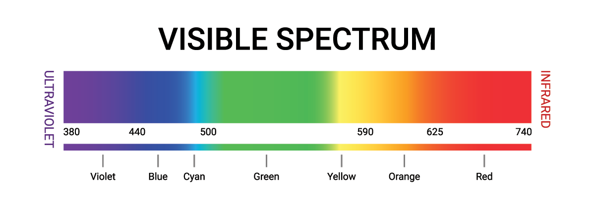
As can be seen from the electromagnetic spectrum red light has the longest wavelength and thus travels the fastest. Based on Snell’s law the amount of bending that occurs depends on the speed of the incident light. As white light is made up of all the colours then red being the fastest will bend the least, violet being the slowest will bend the most. In fact each colour has its own refractive index.
Dispersion is seen any time white light is broken into its different components and a familiar image of this phenomena is seen daily when there is a combination of rain and sunlight.

Check your understanding
View
Polarisation
Evidence of the wave model of light is given by the polarisation of light. Polarisation is a term to describe a restriction on the direction of oscillation of a transverse wave meaning it can only vibrate in one direction.
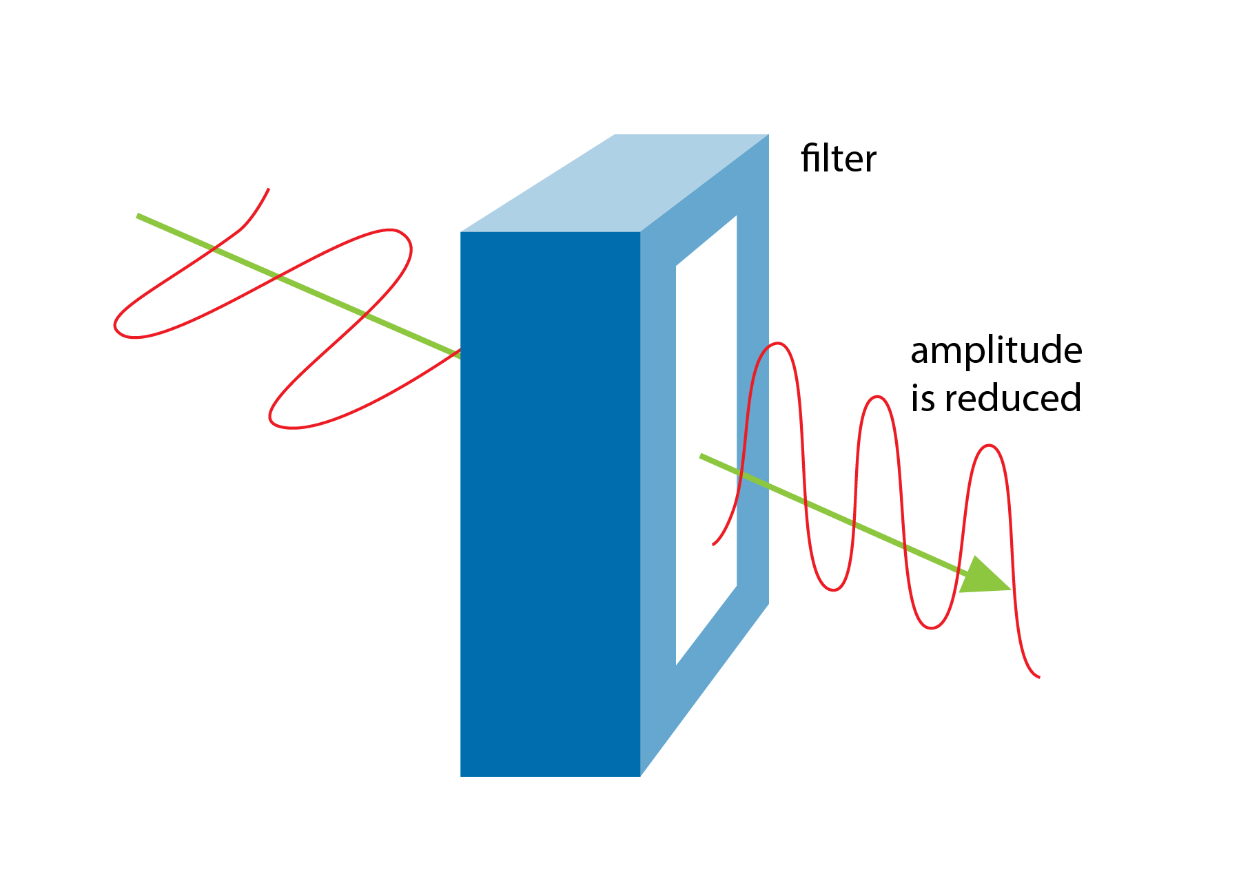
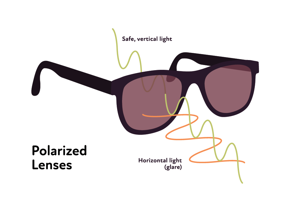
A polarising filter will allow one direction of oscillation to occur and block out all others. The images below show how a polarising filter allows different directions of light waves to travel.
A vertical transverse wave with a vertical filter - this is allowed to travel through. |
A horizontal transverse wave with a vertical filter - this is not allowed to travel through and is completely blocked |
A transverse wave travelling at an angle of \(45^circ\) to a vertical filter - the vertical component can pass but not the horizontal component can travel through. This results in a reduced amplitude passing through . |


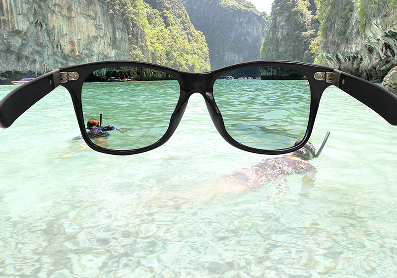
Applications of the polarising of light waves is most commonly seen in sunglasses and window tints. The light from the Sun is completely unpolarised meaning the transverse waves travel in all orientations. Polarised sunglasses act to allow only certain orientations through thus protecting your eyes and reducing glare.
| 
|
Test your understanding of polarisation by answering the following questions.
Check your understanding
View
Young’s Double Slit Experiment and the Wave Nature of Light
Diffraction of Light
Diffraction is a phenomenon that occurs when a wave passes through a narrow opening or around an obstacle. As the wave moves through the gap, it spreads out into a semicircular pattern.

The degree of diffraction depends on two key factors:
- The wavelength of the wave (𝜆, in metres)
- The width of the opening or obstacle (𝑤, in metres)
Greater diffraction occurs when the wavelength is similar to or larger than the gap size, expressed as:
\[\frac{\lambda}{w}≥1\]
where
- \(\lambda\) is the wavelength in metres, \(text{ m}\)
- and \(w\) is the obstacle/gap width in metres, \(\text{ m}\)
This explains why light, which has a very small wavelength , diffracts significantly only when passing through very narrow slits.
Superposition of waves
Superposition describes the vector sum or addition of overlapping waves travelling in the same medium, their displacements add together at every point. This interference of the waves with each other distinguishes the waves from particle behavbiour.
Suppose two baseball players were at training and both threw a ball at the same time as shown in the diagram.
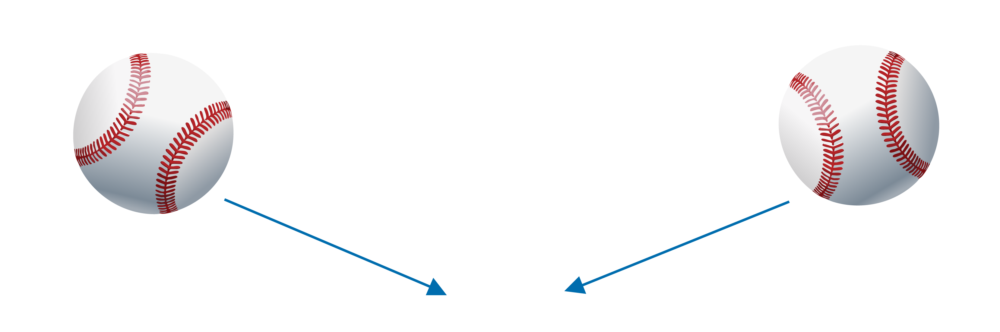
At the point of collision, the balls might bounce off each other or change direction. This is typical particle behaviour.
Now, imagine that instead of throwing balls, the players shout at each other. Their sound waves meet and interfere. The waves don't bounce or deflect but instead combine.
This is the principle of superposition. When two or more waves occupy the same space in a medium, their displacements add together at every point:
Constructive interference occurs when waves are in phase (peaks align), resulting in a larger amplitude.
Destructive interference occurs when waves are out of phase (peak meets trough), partially or completely cancelling each other.
Superposition refers to the vector sum or addition of overlapping waves travelling in the same medium. The result can be constructive, when the waves are travelling with the same sign and will add together, or destructive, when the waves are travelling with the opposite sign and will cancel each other. A diagram is shown below
When waves interact, whether it be mechanical waves or sound waves or light waves the result is not what would occur of the two baseballs but rather a principle called superposition.
Recall that waves are a net transfer of energy without a transfer of matter and so what happens after the waves meet and superimpose to form either constructive, destructive or partially destructive waves, is that they will both continue on their original paths. An example of this is shown below.

Young’s Double Slit Experiment
Before light was considered a wave it was widely accepted that light was made of tiny particles called corpuscles. It wasn’t until Thomas Young performed his famous double slit experiment that it was shown that light actually exhibits the same properties of a wave.
| Prediction based on Corpuscle Theory | Experiment results providing evidence of light behaving as a wave |
|---|---|
| 
|
The image below shows what happens as a light wave passes through one slit.
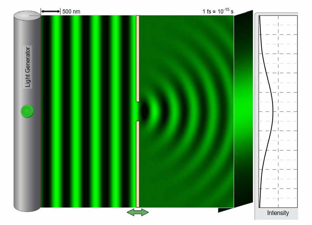
The bending of the light wave as it passes through the opening is an example of diffraction however to an untrained eye this could still give support to the corpuscular theory based on the high intensity seen directly opposite the opening.
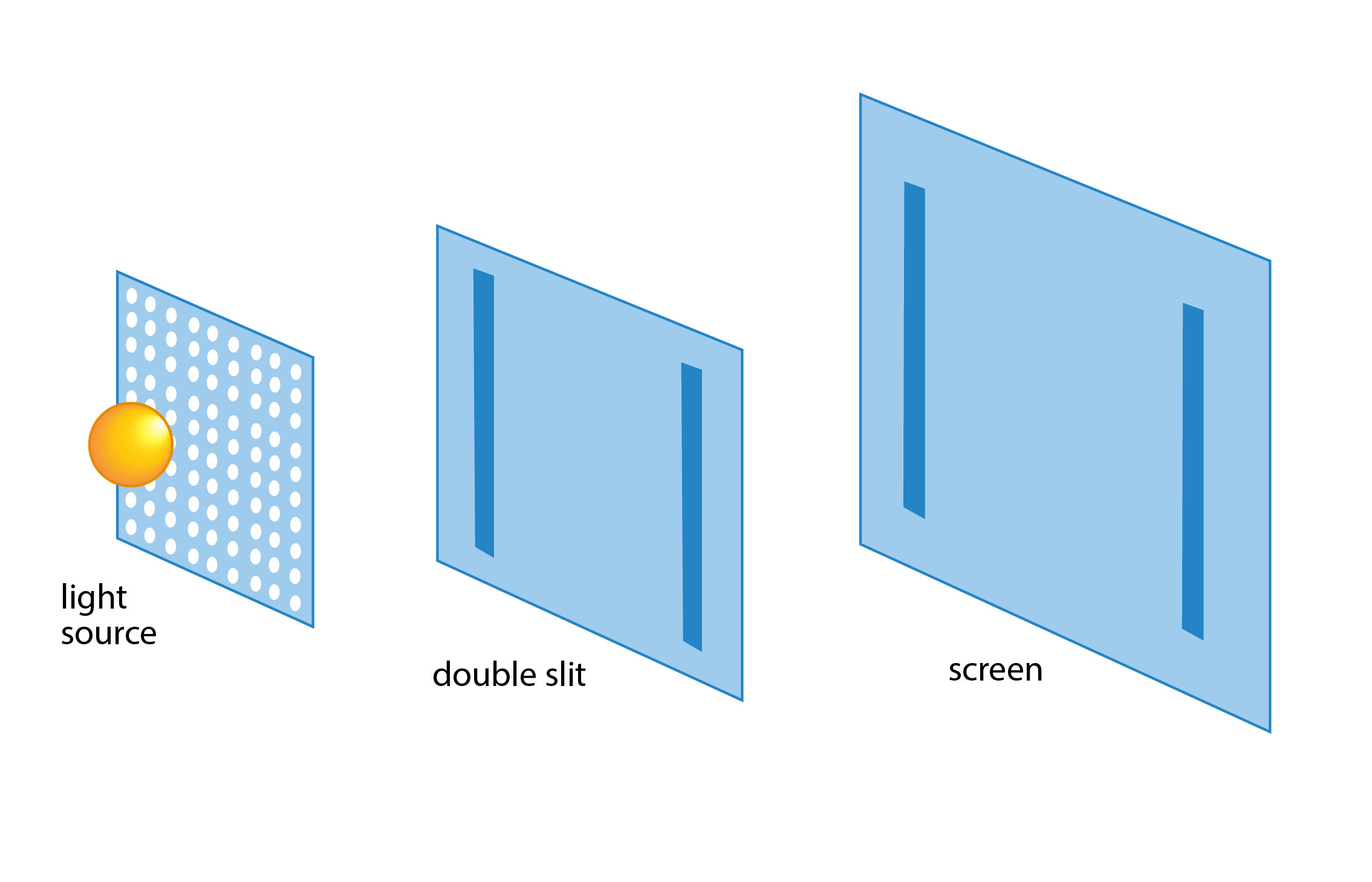
Young’s Double Slit experiment is so famous due to what happened when another barrier was included.

What was seen is a result only a wave model could predict! Young suggested that the incident light, which was a monochromatic light source, must be a plane wave. As it passes through the narrow slits the wave would diffract through two obstacles that would cause two semi-circular waves to form which would then interact, superimpose and form constructive and destructive interference. The bright bands recorded were a result of constructive interference which are also known as antinodes or an antinodal line and the dark bands were a result of destructive interference, also known as nodes or nodal lines.
To appreciate how the antinodal and nodal lines (bright and dark regions) occur is to take a closer look at how the wave travels from the slit opening to the recording screen. As the two waves pass through the two slits, directly opposite the central point is a bright spot because both waves reach the screen at the exact same time, the difference in the distance both waves took is called the path difference. The other regions of dark and bright spots can be considered by calculating the path difference as shown in the image below.
Complete constructive interference (bright spots) will occur when the path difference, \(p.d = nλ\), where \(n\) is \(0, 1, 2, 3\), etc. \(n=0\) refers to the central bright band and \(n=1\) is the next corresponding bright spots, \(n = 2\) the second set of bright fringes and so on.
Complete destructive interference (dark spots) will occur when the path difference, \(p.d = (n+\frac{1}{2})λ\), where \(n = 0\) is the first region of dark spots, and \(n = 1\) is the region between the first and second pair of bright spots and so on.
To summarise bright regions occur when the p.d is an integer multiple of the wavelength and dark regions are when there is a p.d of \(\frac{λ}{2}\).
Effect of slit spacing, distance from screen and wavelength
The distance between the bright bands and dark bands are known as fringe spacing \(Δx (m)\). \(Δx\) depends on multiple variables including the wavelength \(λ(\text{m})\) i.e colour of monochromatic light, distance from the slits/obstacles to the screen \(L (\text{m})\) and the distance between the slits \(d(\text{m})\).
It was observed that an increase in wavelength or distance to the screen caused an increase in fringe spacing along with a decrease in the distance would also cause an increase in fringe spacing.
To calculate fringe spacing therefore the following formula can be used.
\[Δx = \frac{\lambda L}{d}\]
Young’s double slit experiment provided evidence for the wave nature of light. It showed evidence for diffraction and superposition both being supported by wave theory.
Test your knowledge of Young’s Double Slit experiment by answering the following.