Lenz’s law and its applications
Electromagnetic induction has wide-ranging applications, most notably in both AC and DC generators, and in the transmission of electrical power through transformers.
In the previous section, Faraday’s law was used to quantify the size of an induced emf. To complete the analysis, we now turn to how to determine the direction of the induced emf and current.
Use this page to revise the following concepts within Lenz’s law and its applications:
Lenz’s law
When a changing magnetic flux passes through a coil, it induces an emf, and if the circuit is closed, a current. Faraday’s law gives the magnitude of this emf, while Lenz’s law and the right-hand grip rule determine the direction of the resulting current.
Lenz’s law states that the induced emf will always give rise to a current whose magnetic field opposes the direction of the original change in flux.
To apply Lenz’s law:
- Determine the direction of the change in flux
- Invoke Lenz’s law, where the induced current will have a magnetic field opposite to this direction
- Use the right-hand grip rule to determine the direction of current flow
Worked Example
A single coil is moved from a region with zero magnetic field to a region of a magnetic field whose direction is into the page when viewed from above, as depicted below.
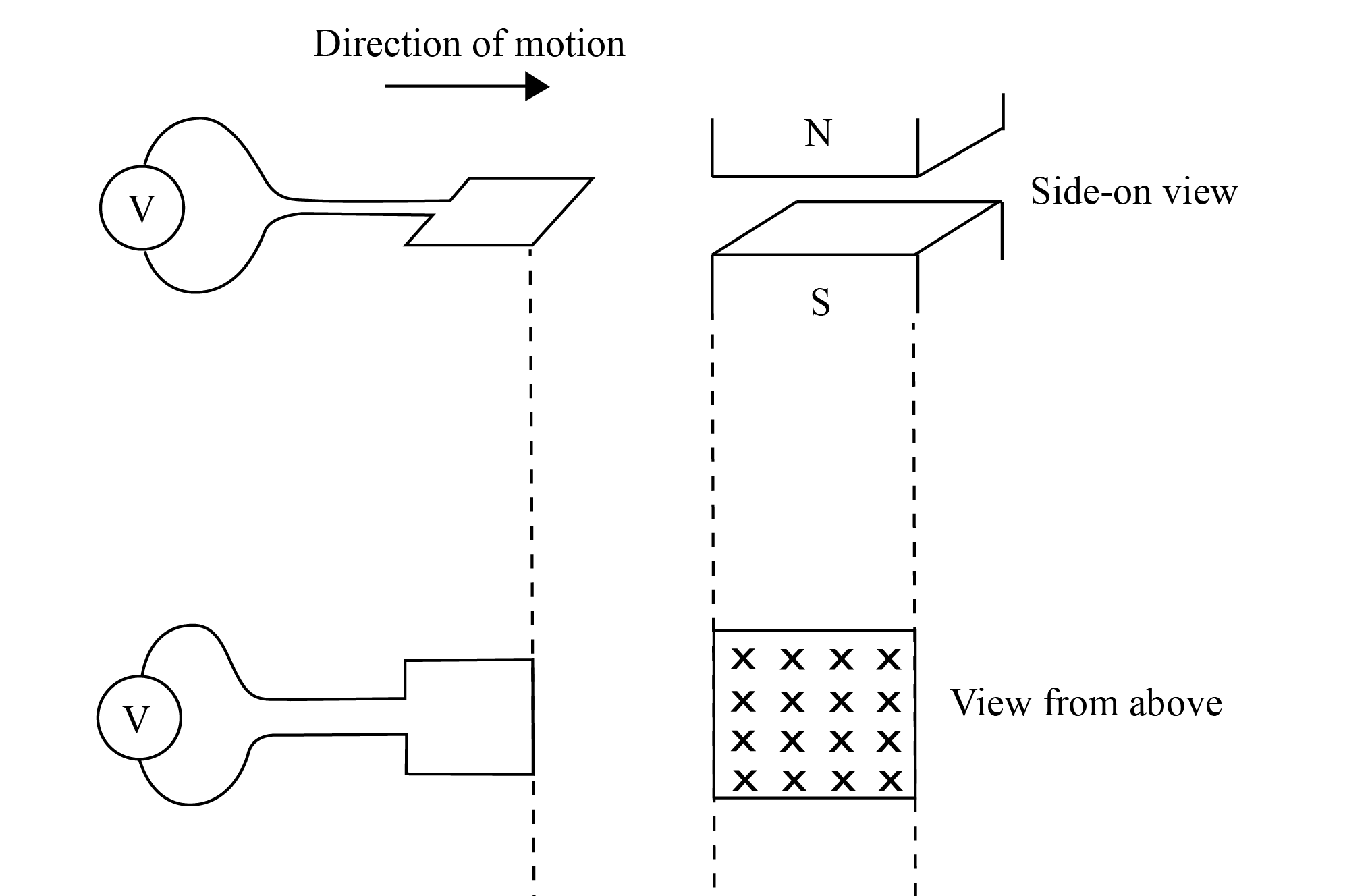
To determine the direction of the current:
- Determine the direction of the change in flux:
The flux through the loop is initially zero. Then it is into the page. So the direction of the change in flux is into the page. - Invoke Lenz’s law, where the induced will have a magnetic field opposite to this direction:
The induced current will produce a magnetic field opposite to this – out of the page. - Use the right-hand grip rule to determine the direction of current flow:
Using the right-hand grip rule, with the thumb pointing out of the page, the fingers curl in an anti-clockwise direction.
Hence the induced current flow anti-clockwise when viewed from above.
Check your understanding
View

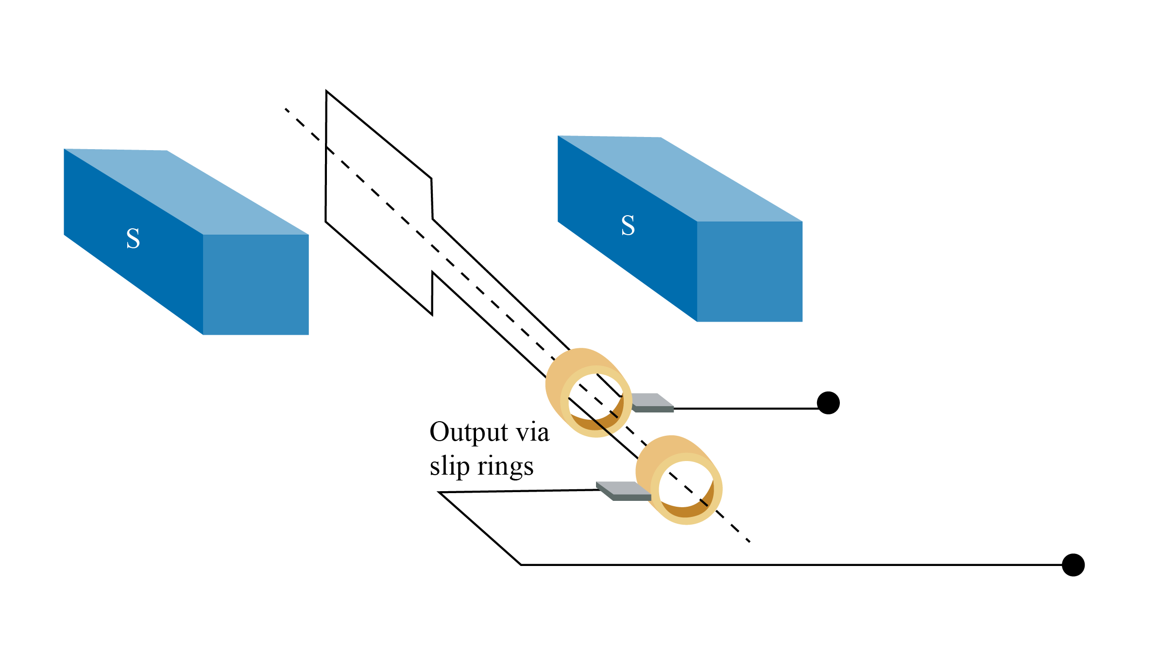
AC generation
A generator is a device that uses a rotating coil inside a magnetic field to induce a current in the coil. An alternator is a type of generator that produces an alternating current (AC). Click on the image below for more details of AC generators.
One of the most common uses of an alternator is in a car. When the car is running, the engine spins the alternator via a drive belt, generating electricity to charge the battery. This ensures the battery remains charged while the car is in use.
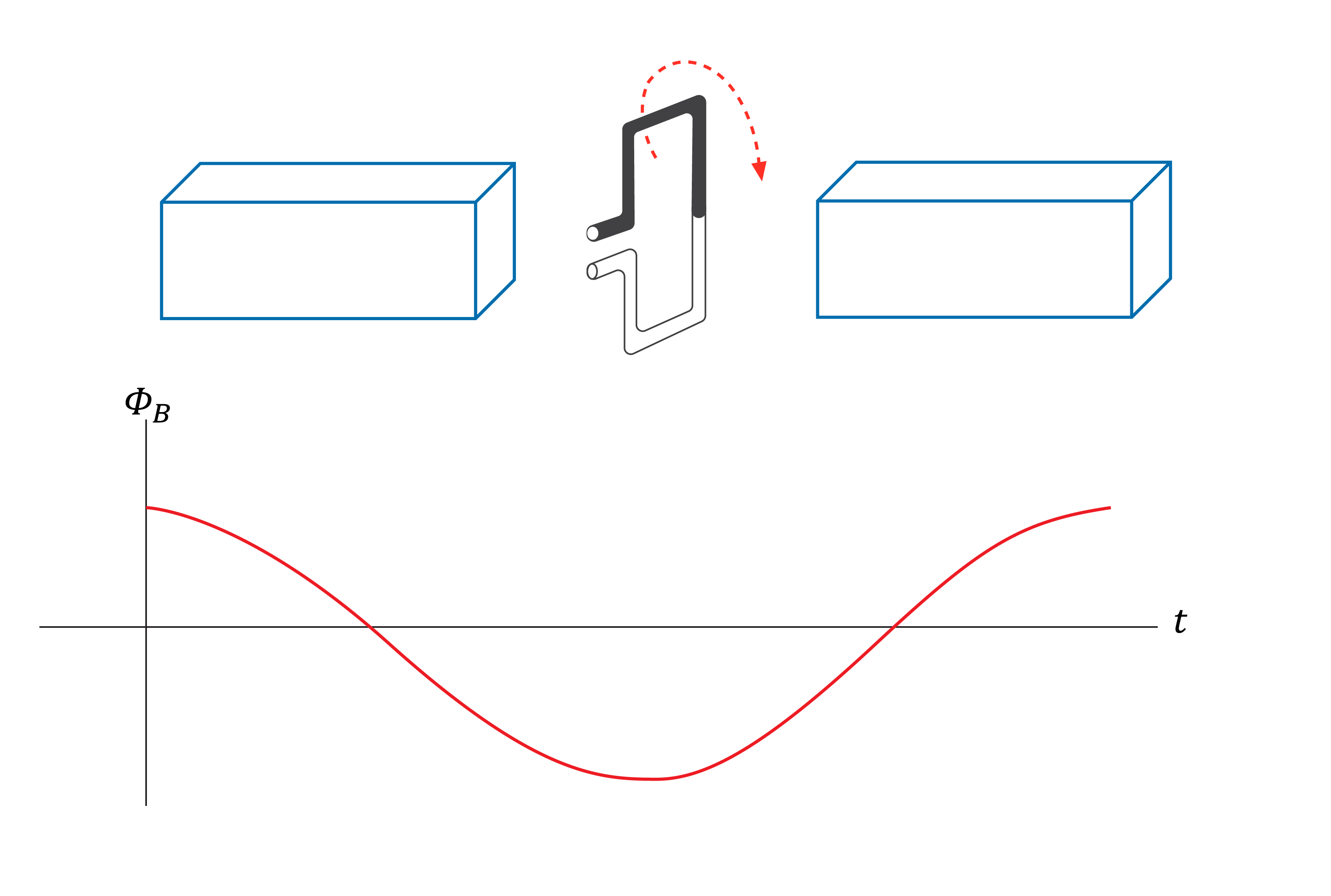
To understand how the flux and induced emf vary as the alternator rotates, we can consider the \(\Phi - t\) and \(\varepsilon - t\) graphs as the coil in an alternator rotates through 360°.
If the frequency of rotation of the coil in an alternator is increased, this has two effects on the emf graph:
- The period of rotation decreases – the graph is contracted horizontally
- The amplitude of the graph increases – a smaller time period results in greater emf as per Faraday’s law.
Worked Example
An alternator consists of a square coil of 10 turns connected to slip rings. It rotates at a frequency of \(20 \text{ Hz}\). It is entirely within an external magnetic field of magnitude \(4.0 \times 10^{-3} \text{ T}\).
Determine the magnitude of the average emf induced in the coil as it completes a quarter turn from the position shown.
Solution
Determine the change in flux \(\Delta \Phi\)
In one quarter turn the flux goes from maximum to zero. \(\Delta \Phi =0-4 \times 10^{-3}=-4 \times 10^{-3}\).
As the direction is not necessary \(\Delta \Phi=4×10^{-3} \text{Wb}\).
Determine the time \(\Delta t\)
The frequency of rotation is \(20 \text{Hz}\). So one full revolution occurs \(\frac{1}{20}=0.05 \text{ sec}\).
A quarter rotation will be \(0.05÷4=0.0125 \text{ sec}\).
Use Faraday’s law
\[\begin{align} \varepsilon &=N \frac{\Delta \Phi}{\Delta t} \\
\varepsilon &= 10 \times \frac{4 \times 10^{-3}}{0.0125} = 3.2 \ \text{V} \end{align}
\]
Check your understanding
View
DC generation
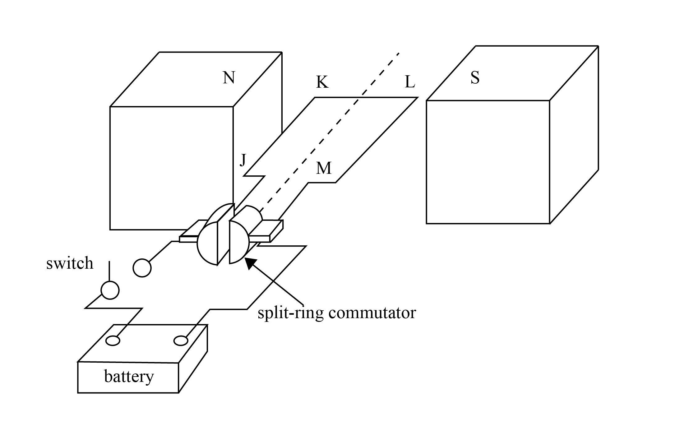
DC, or direct current , refers to a current that flows in only one direction through the circuit. An AC generator can be converted into a DC generator with a simple modification.
By replacing the slip rings with a split-ring commutator, the generator produces a DC current. A split-ring commutator reverses the direction of current through the external circuit by swapping the connections to the rotating coil every half turn. This ensures that the output current always flows in the same direction, as detailed in the diagram below.
NoteBoth the AC and DC generators can have their efficiencies further improved by using multiple pairs of magnets arranged evenly around the rotating coil. This ensures that when one set of magnets produces little or no emf, another set is still inducing emf in the coil. The result is a smoother emf output, with fewer fluctuations and a waveform that is closer to a continuous or constant value. This improves the overall consistency and usability of the generated current. |