Activity Networks and Precedence Tables
Activity Networks and Precedence Tables
Activity networks are graphical representations where edges denote activities or tasks, typically labelled with weights to represent the time required to complete the activity. Vertices signify the connections between activities, illustrating dependencies and task flow. For example, if activity C depends on the completion of activities A and B, the network would feature two edges representing A and B into a vertex, with an edge for C from that vertex, as represented by the image below. This structure effectively visualises dependencies, identifying A and B as the immediate predecessors of C.

Activity networks serve as the foundation for applying network mathematics to optimise scheduling problems. They can be constructed using precedence tables, which summarise the connections and dependencies between tasks. A precedence table typically consists of two columns: one listing the tasks or activities and the other identifying the immediate predecessors for each activity.
An example of a precedence table is given below:
| Activity | Immediate Predecessor |
|---|---|
| A | - |
| B | A |
| C | B |
| D | A, C |
| E | B, D |
| F | B, D |
| G | E, F |
An activity network can be constructed from a precedence table by systematically examining the immediate predecessors and connecting them in a network diagram. Activities without immediate predecessors are the starting points in the network, originating from the starting vertex. Similarly, activities without successors lead to the ending vertex, marking the completion of the network.
In some cases, an activity may share some, but not all, immediate predecessors with another activity. To accurately represent such dependencies, a dummy activity is introduced into the network. A dummy activity is a placeholder that is represented by a dotted edge. It has no actual task associated with it and is always assigned a weight of 0, as it serves solely to represent the connection without contributing to the overall time or cost of the project.
This can be illustrated in the following activity network, where there is a dummy from activity A to D. This means that activity D has immediate predecessors A and C.

Worked Example
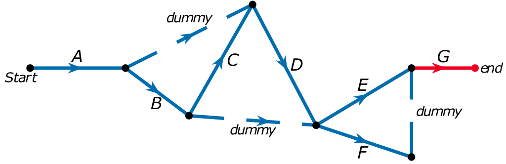
Construct an activity network from the following precedence table:
| Activity | Immediate Predecessor |
|---|---|
| A | - |
| B | A |
| C | B |
| D | A, C |
| E | B, D |
| F | B, D |
| G | E, F |
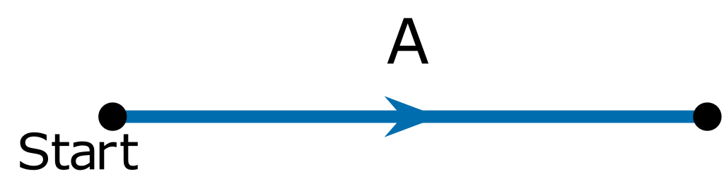
To construct the activity network, we begin with the starting vertex and label the activity that does not have any immediate predecessors.
Next, we include activities that follow without shared predecessors. For example, activities B and C can be added directly as they do not share dependencies.

Activity D has two immediate predecessors: A and C. Since A is also a shared predecessor with B, a dummy activity is required to accurately represent these dependencies. As edges in a network are generally represented with straight lines, the network can be adjusted to maintain the same information whilst including the dummy activity.

For Activities E and F, which share all their predecessors (B and D), they can come out from the vertex where B and D go into. However, B is also shared with Activity C, requiring another dummy activity to connect B to the vertex with D. The network should again be adjusted to account for this dummy activity while preserving logical flow.

Finally, Activity G, the only remaining activity, becomes the end activity. It depends on both E and F, which share the same vertex. In this case, a dummy activity is introduced to ensure the dependencies are represented correctly.